

For those of us who like to tinker and work on various projects, learning new things and creating various contraptions, it seems there’s a large selection of specialized tooling available. Some of those machines can be very versatile, but also costly. Thankfully, there’s also a selection of an entry-level variants, be it cheap laser cutters, or – something I’ll focus on in this mini-series – CNC machines.
I wanted to build one, with a goal not to be able to manufacture large pieces, but to learn and have fun, at a fairly low cost, understanding what it means with regards to capabilities of such machine.
I’m going to share my experiences with hobby CNC kit in 3 parts:
- Assembly (this article) – turning bag of parts into working machine,
- Review and usage – what I like and dislike, how is the machine performing – check it out for more opinions about the quality of the kit, experiences with support, but also information about various tools I used,
- Upgrades and improvements – adding limit switches and 3D printed parts to increase functionality,
Let’s begin.
What are we building?
There are many similar models available, following the same design, but with various small differences between units – mostly when it comes to the work area size, accessories, etc. You can buy those as a set ready for assembly, or use as an inspiration and purchase the parts separately, leaving you with the freedom to make changes to the design.
However, those kits are very reasonably priced, and the convenience of having most of the pieces (or more precisely – the minimum set of pieces required to make it work – more about that later) is hard to deny.
This is the variant I’ll be building (model 2418 – work area of 24cm x 18 cm):

I picked the base set on Amazon:
One thing I’d like to call out – I purchased from seller twowin. And I wanted to share that, since – as you’ll find out below – I had to contact them for a bit of support, and they’ve been great, very responsive and helpful (thank you, Mary! 🙂 ).
If you’re browsing similar models, you’ll notice few things:
- The models 1618, 2418, 3018 etc. are all very similar, and vary only in the work area size,
- Some come with ER11 collet – handy for easier swapping of the bits, and will allow you to mill thinner pieces without the need to use additional material underneath (since the bit will be closer to the bed),
- There are also models with 500mW – 5W laser modules – you can find sample videos on YT – seems cool, but I didn’t invest in that option, in hopes that maybe one day I’ll get 40W+ laser… Time will tell 😉
Pick the one that works best for you.
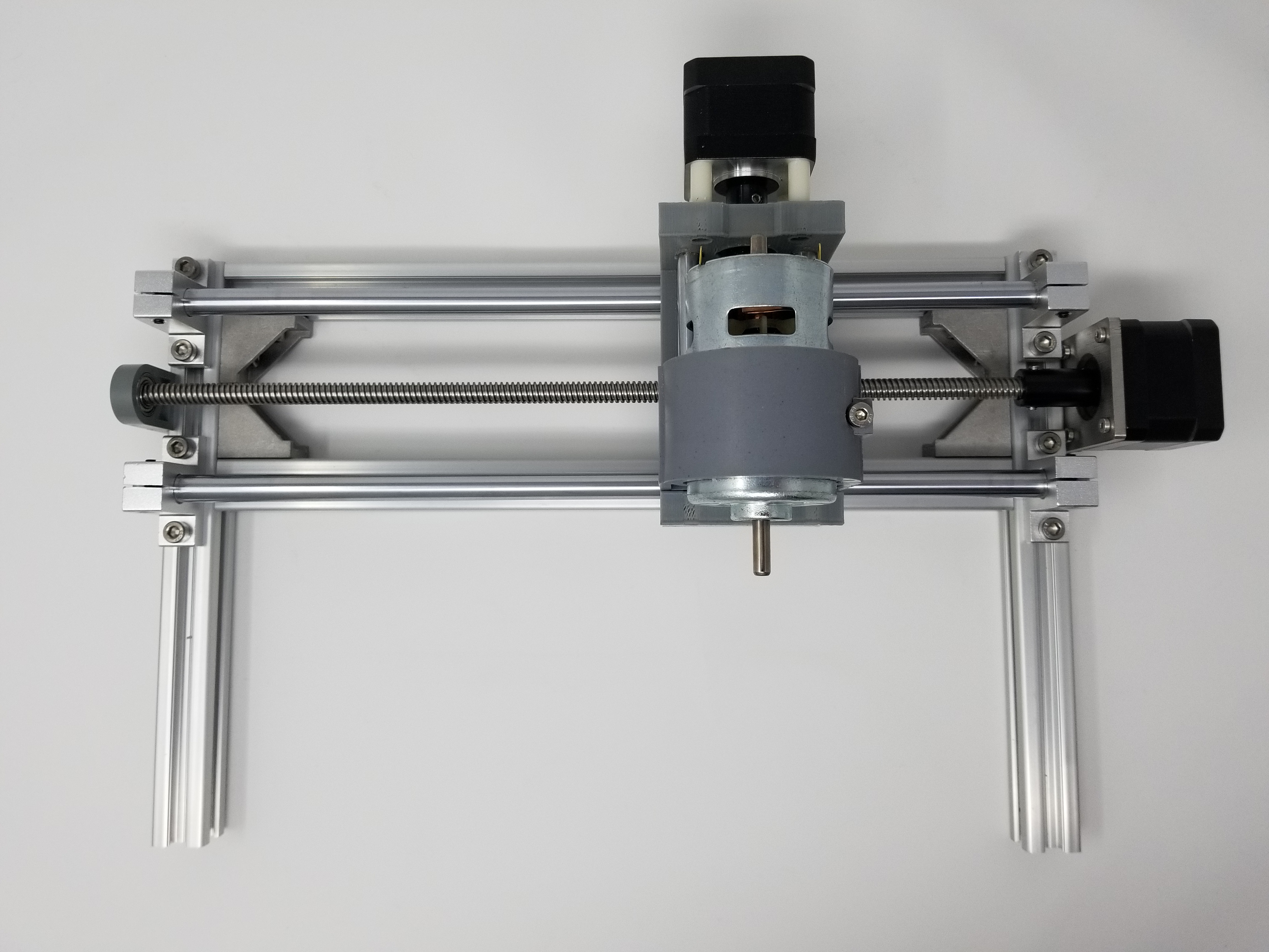
Not to get too much ahead, but rather to encourage you 😉 let’s take a quick look at how the finished machine looks like:

Alright, time to build this thing!
Assembly
Kit arrived packed nicely, although the box was in a very rough condition (and packed in another box for shipping). There were no missing pieces (well, kind of – some pieces were different than referenced in manual, but it didn’t affect the functionality).
All parts were spread into 3 trays:
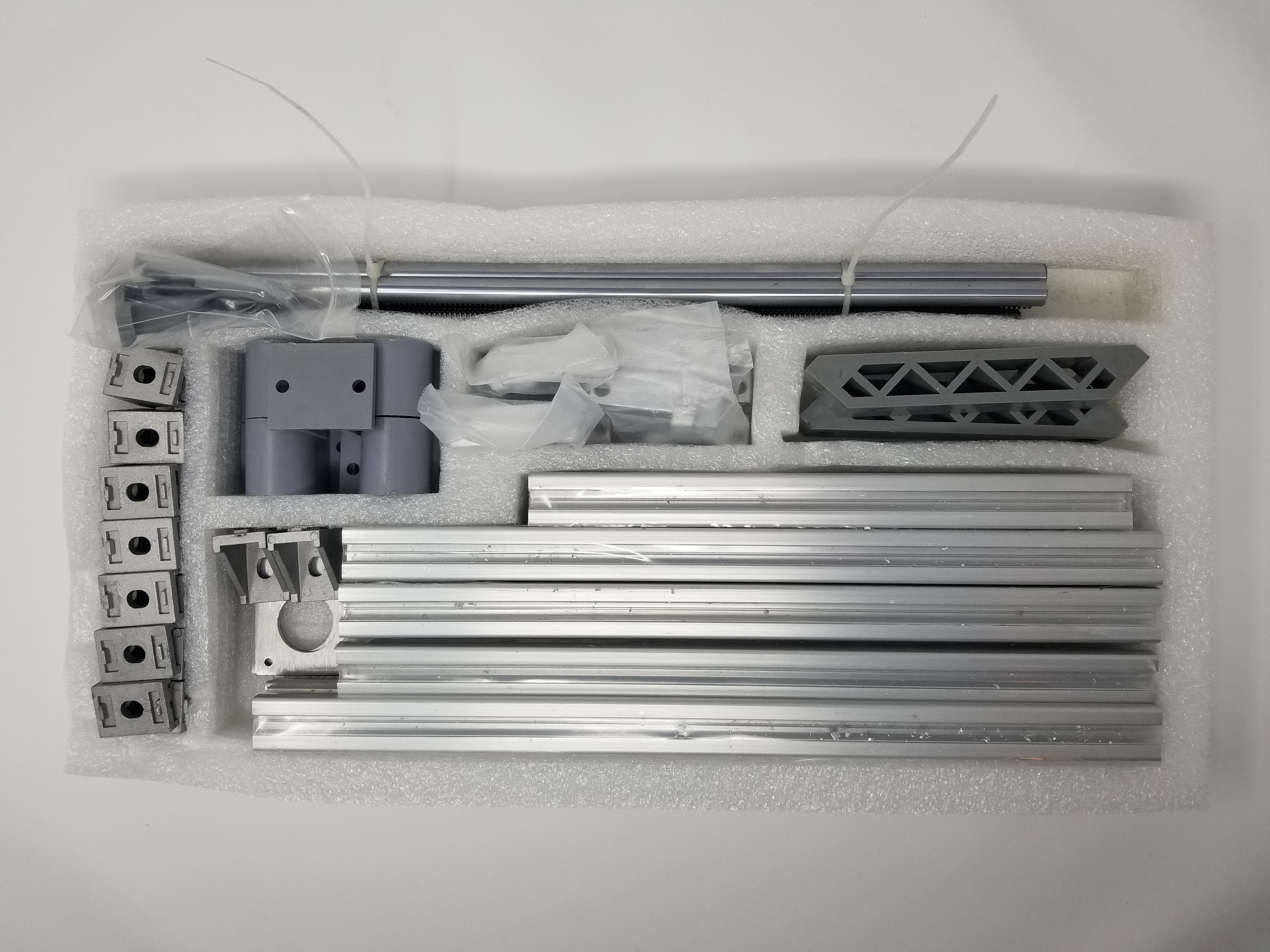
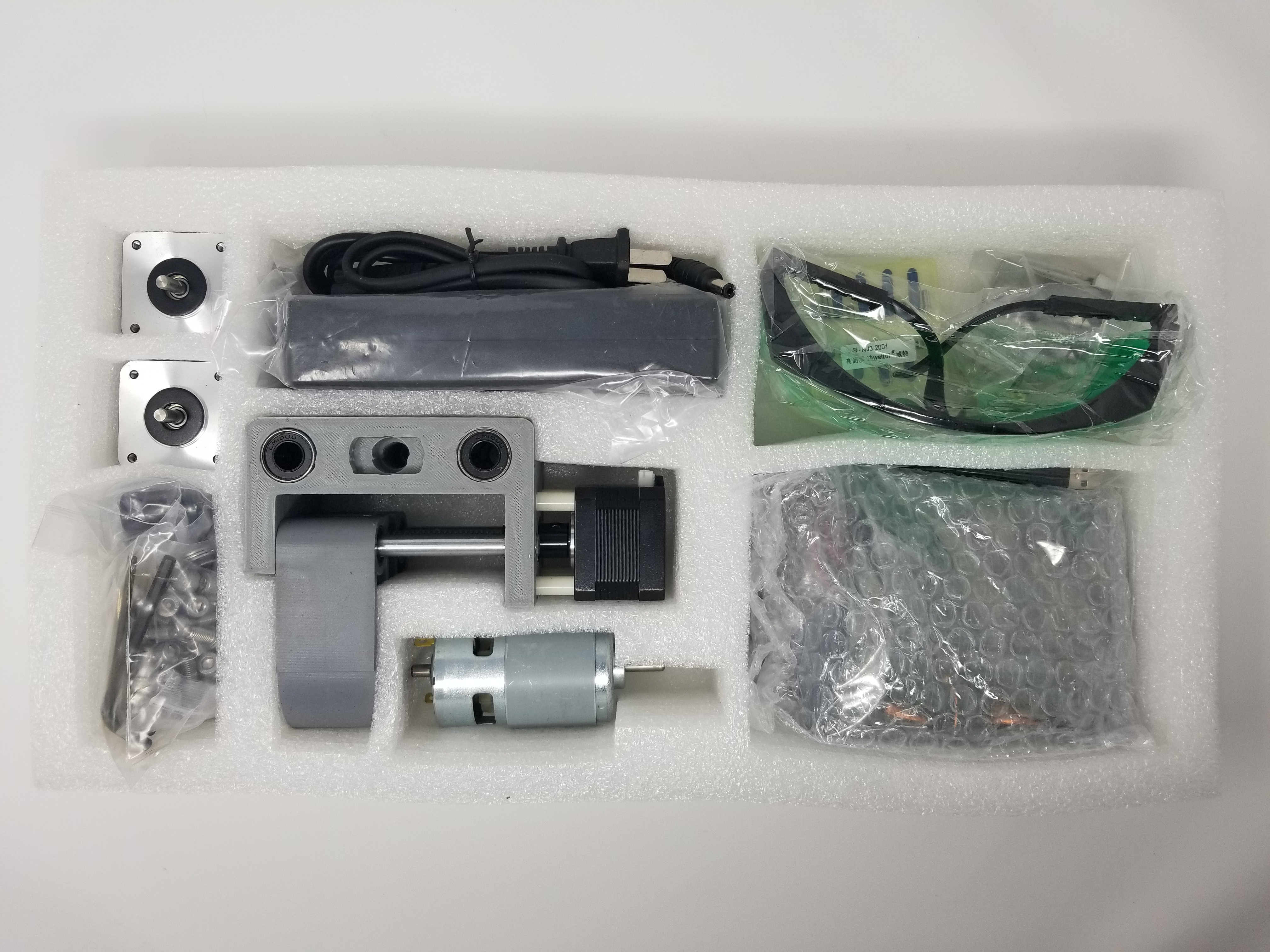

And here are all the parts ready for assembly:

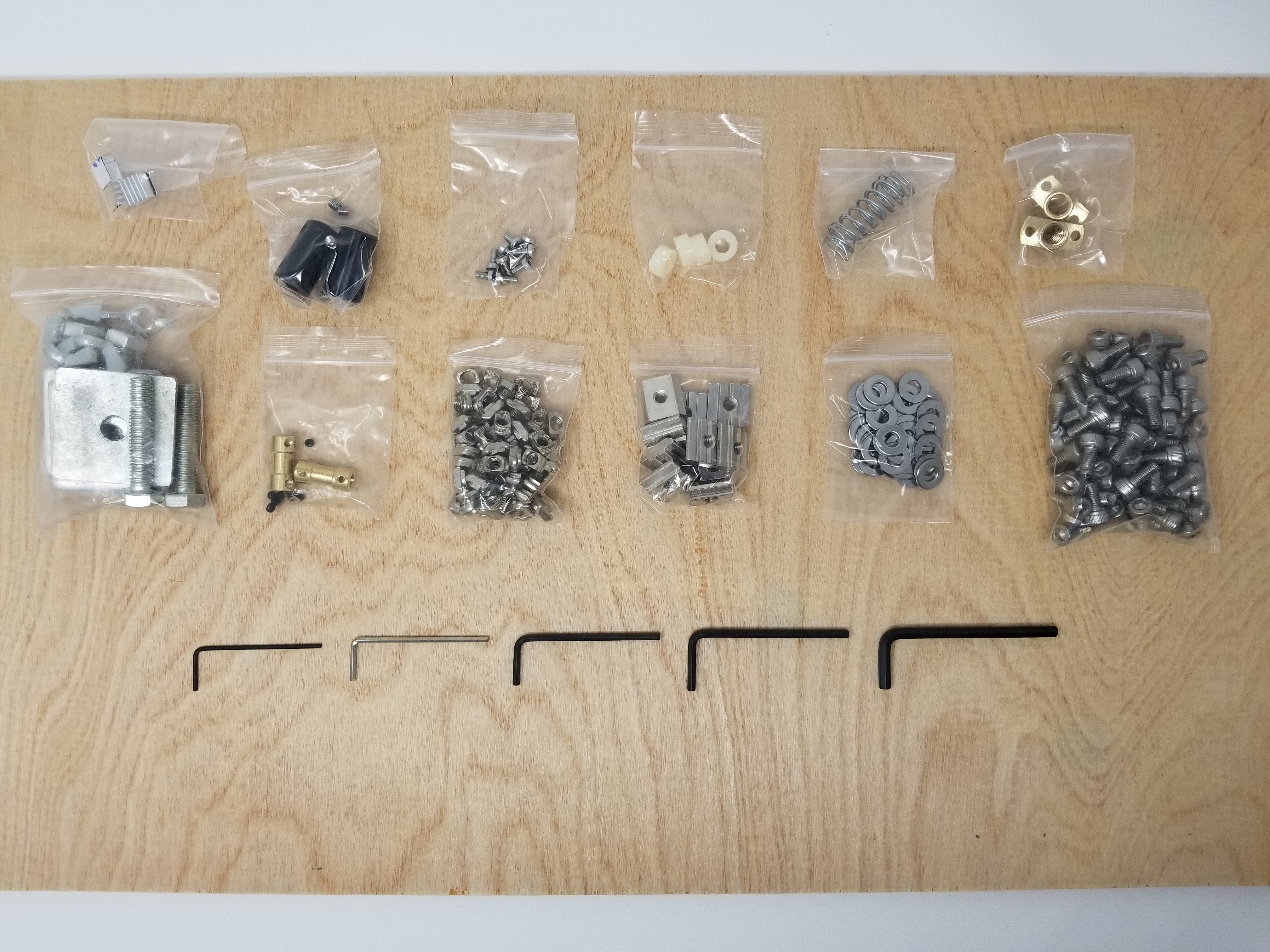
Notice that it also comes with the Allen (hex) keys in all the sizes required for assembly.
Depending on where you purchase the kit from, you may have a CD with software and instructions, or be given a link to download manual and an example assembly video (those can be easily found on YT).
When preparing for the assembly, I found few discrepancies between the manual and the contents of the set:

Notice that it calls out different screw sizes, but the ones provided were all the same. Everything still fits in the end (none of them are too short or too long), so don’t let that confuse you, and don’t waste time searching for different ones 🙂
Assembly starts with 2 frames – one for base, and then vertical one for Z axis, where the spindle will be attached:
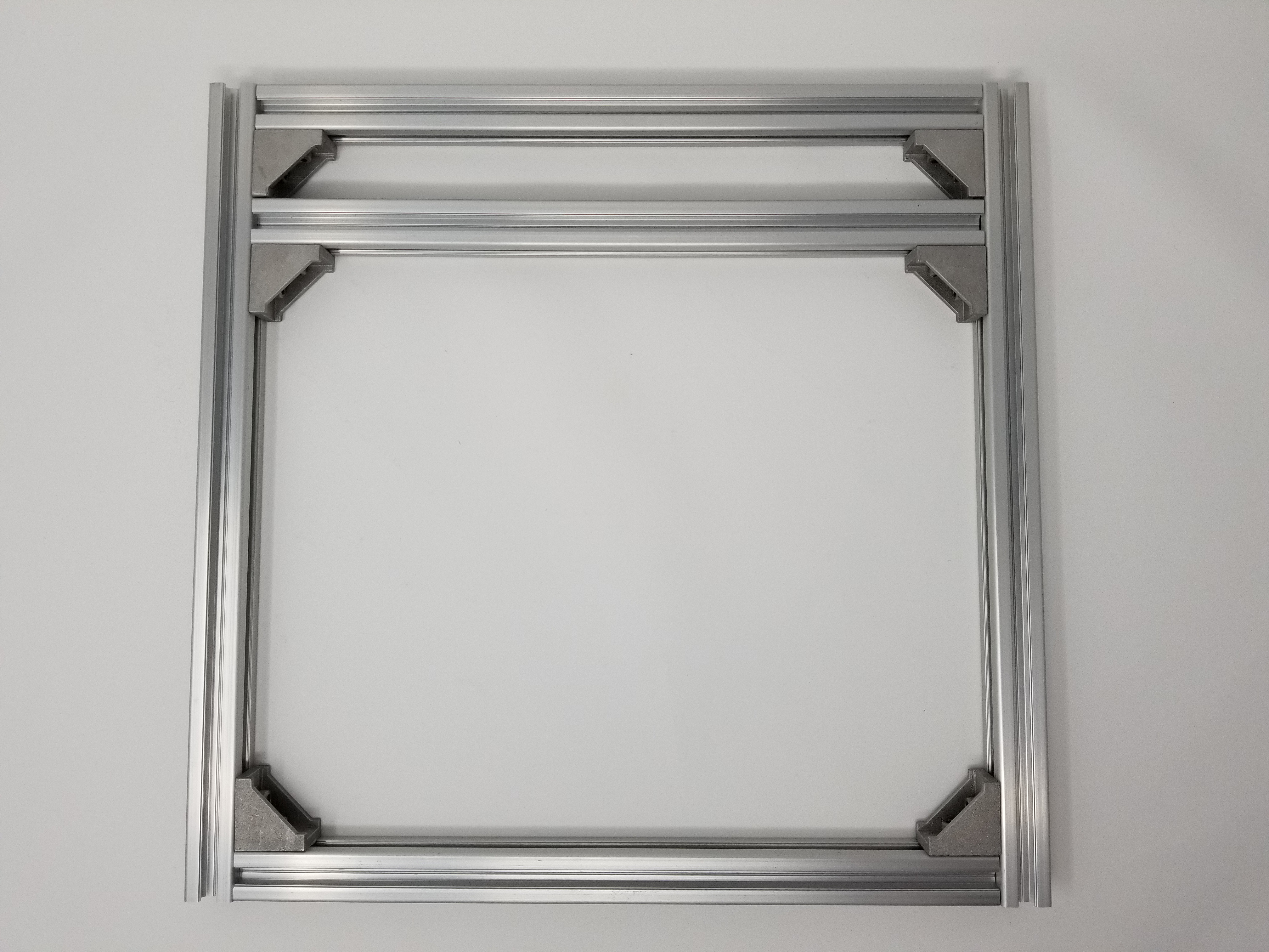

This part is not difficult, once you try the first few T-nuts, you’ll understand how to use them most efficiently – sometimes they may not properly latch onto the extrusions, but it’s easy to spot when that happens. The fix is simple: loosen it up, and try tightening again, hopefully this time they will twist as expected and latch.
I recommend performing the assembly on a flat surface, so you can get all the angles straight.
Some assembly videos you may find online show first assembling the complete frame (meaning, screwing the 2 pieces you see above together) and the adding everything to it, but I found it most convenient to assemble them separately, and then simply attach the vertical part with spindle and Y axis motor to the base.
Next one is the bed. Refer to the photos to see which side is top, and then align the guides at the bottom, but don’t tighten them just yet – we’ll make sure they’re at the right position after adding the guide rods. It helps to use calipers to properly center everything – refer to the manual for exact dimensions.
Be sure the bed can move freely and without much resistance before finally tightening all the screws.
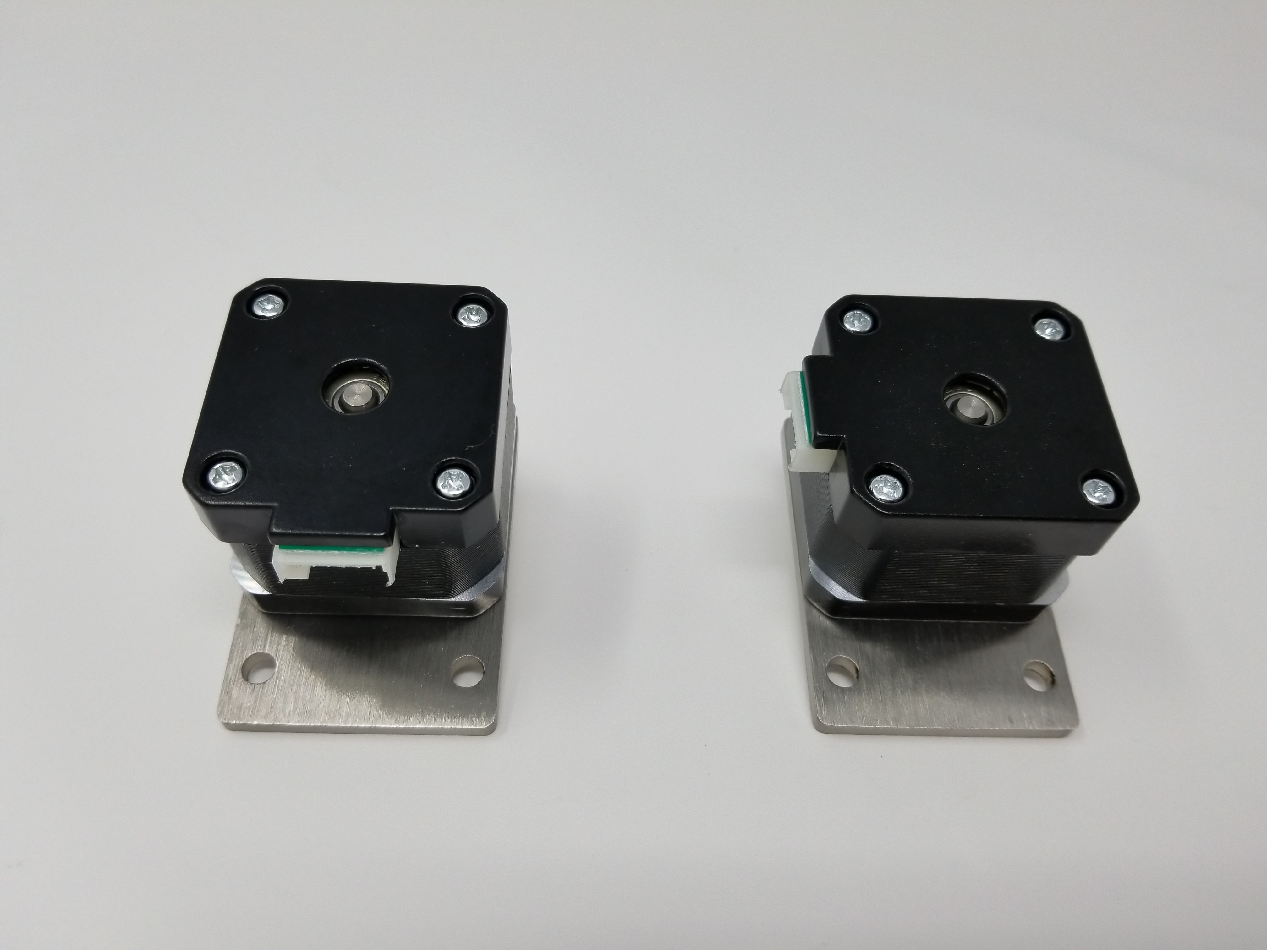
When it comes to mounting stepper motors, it helps to plan ahead – where should the connectors be to allow for easiest cable routing? Here’s how I mounted mine (X axis on the left, Y axis on the right):

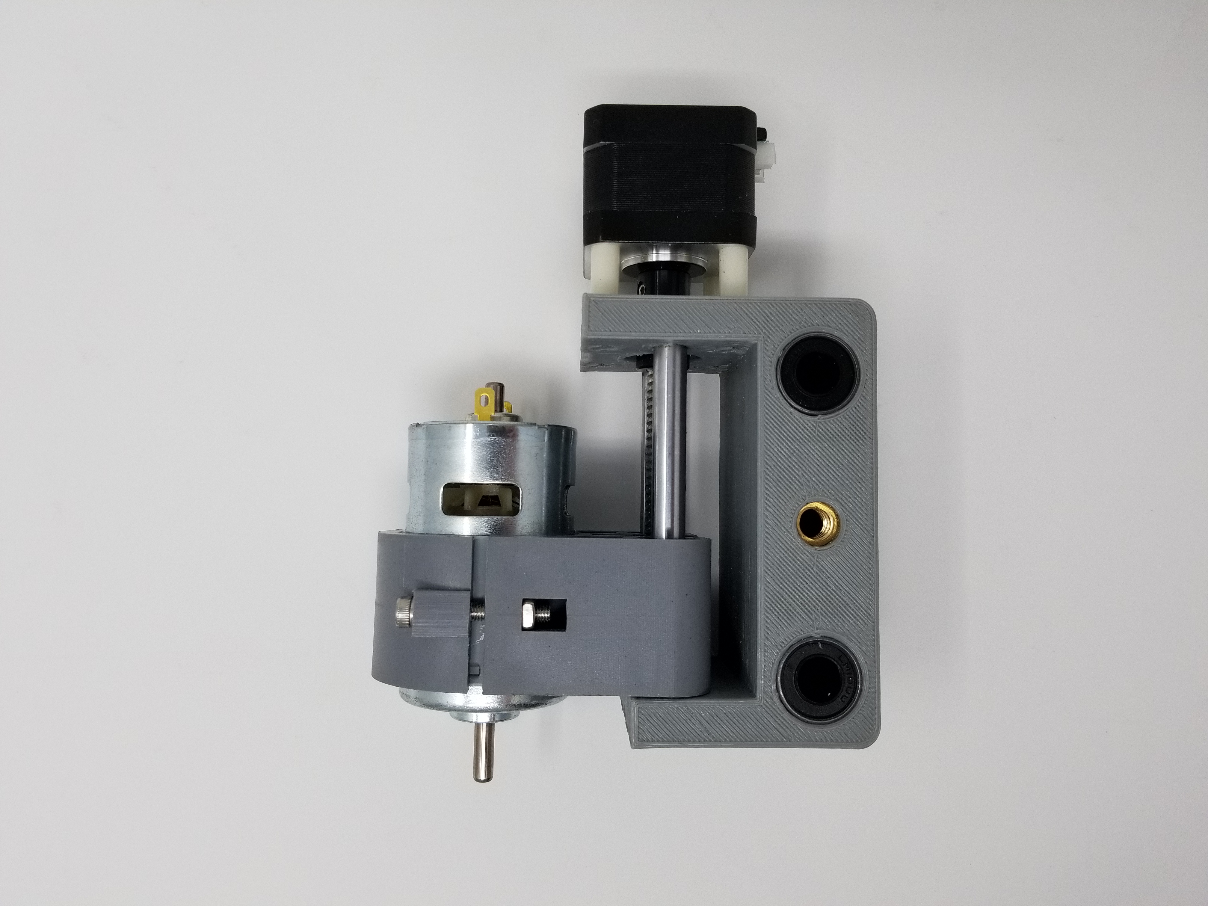
The spindle holder comes already assembled (with stepper motor for Z axis and guide rod), you we only need to insert the spindle. This part takes a lot of force… At some point I was wondering if I should remove the metal collar around the spindle (sorry, I didn’t take a photo of it), but turned out it’s not necessary and it will fit with enough force. I strongly recommend inserting the spindle into the mount before attaching the mount to the rails – it’s just easier this way, since you can get better grip.
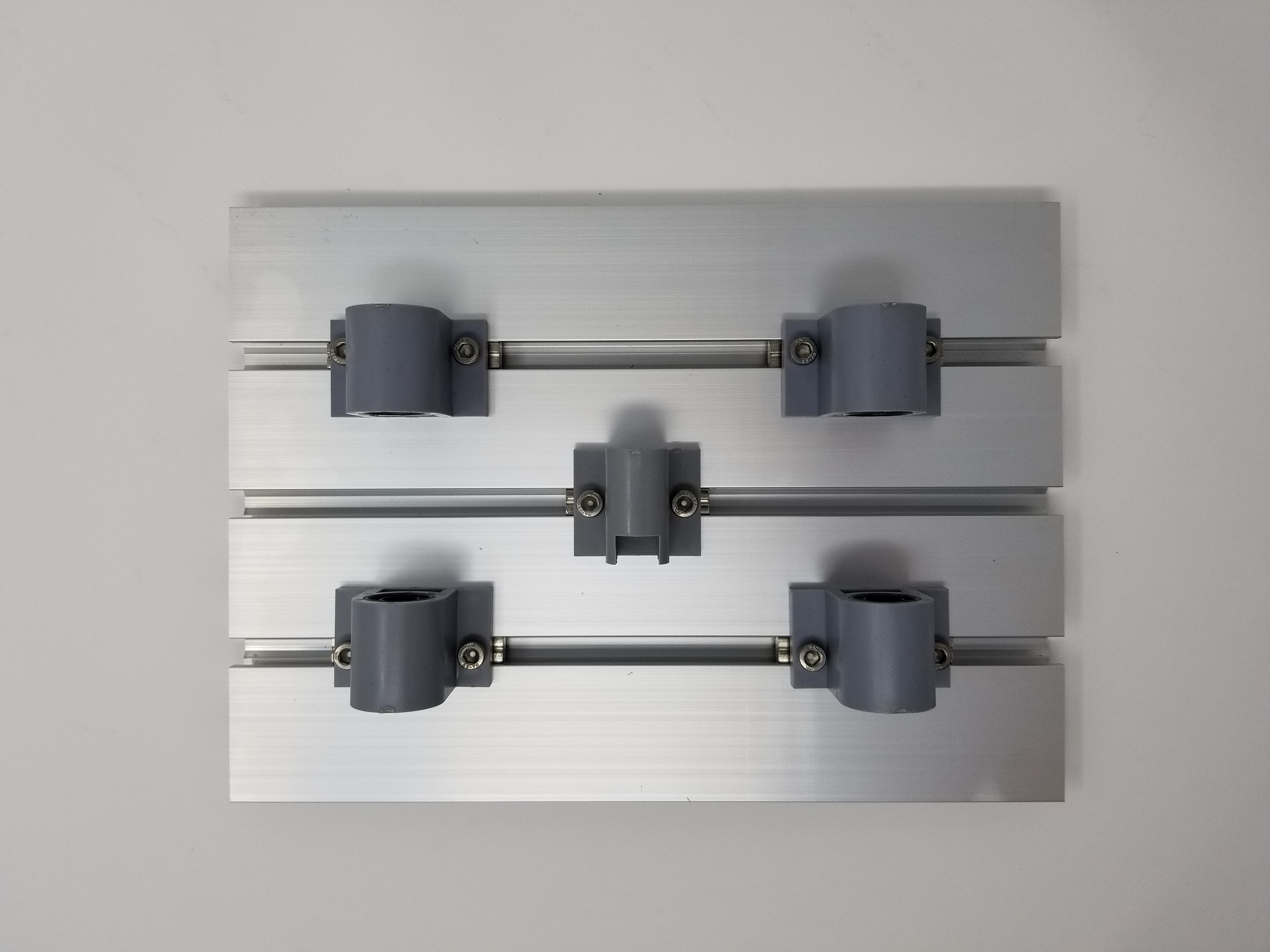
Tip: when attaching the guide rail end holders into aluminum extrusions for X axis, I recommend putting the screws (used to tighten arm around the rod) on opposite ends for top and bottom rod, so that they can be accessed if needed later on. Notice that there will be threaded rod inserted between them, which would limit the space, thus I suggest inserting screws from the “outside” (meaning, screw from top for top rail mount, screw from bottom for bottom mount).
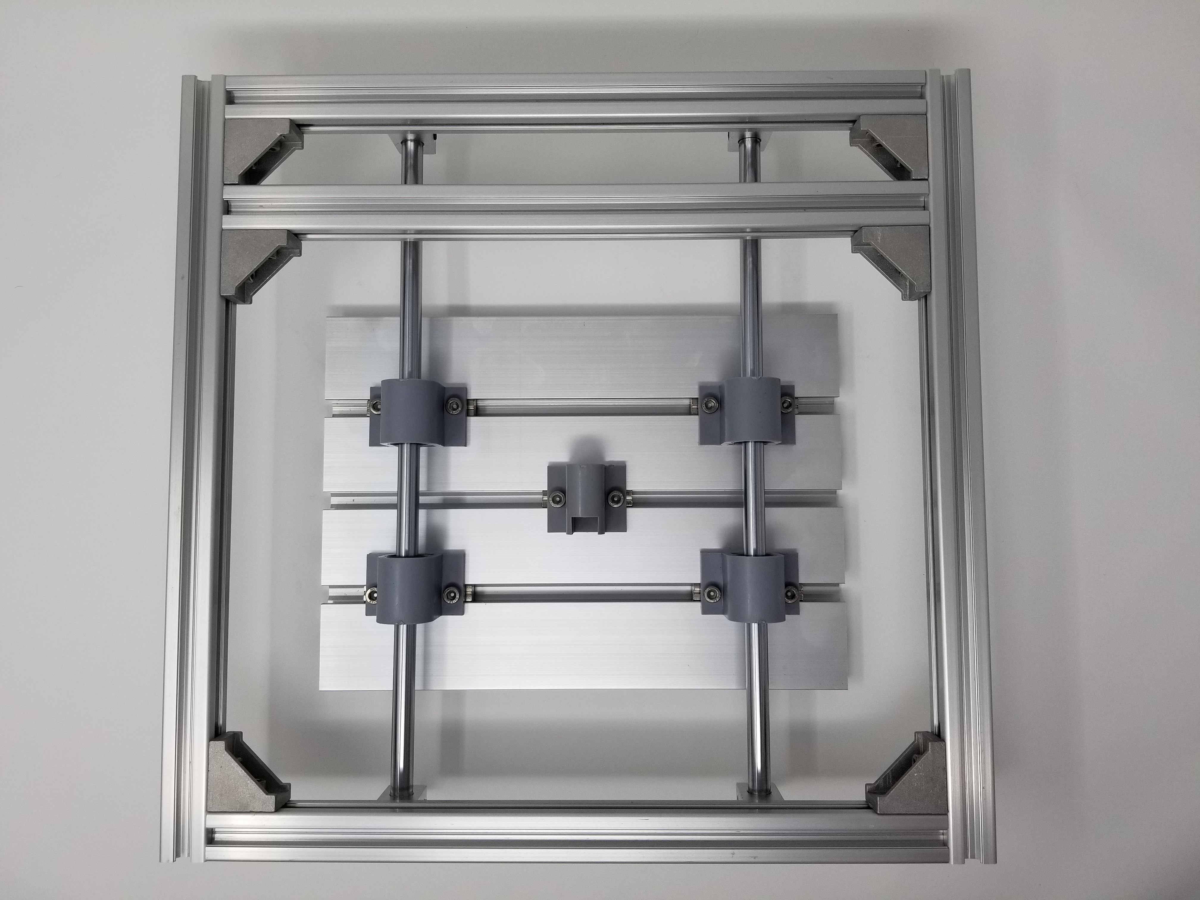
Then just attach it to the upper part of the frame, along with stepper motor for X axis:
Last step is simply connecting the 2 halves together – again, refer to the manual for exact dimensions (position from the edge – it’s pretty much aligned with the crossbeam in the base), to ensure you’re making use of the maximum size of the work space.
And this is what we should have in the end:
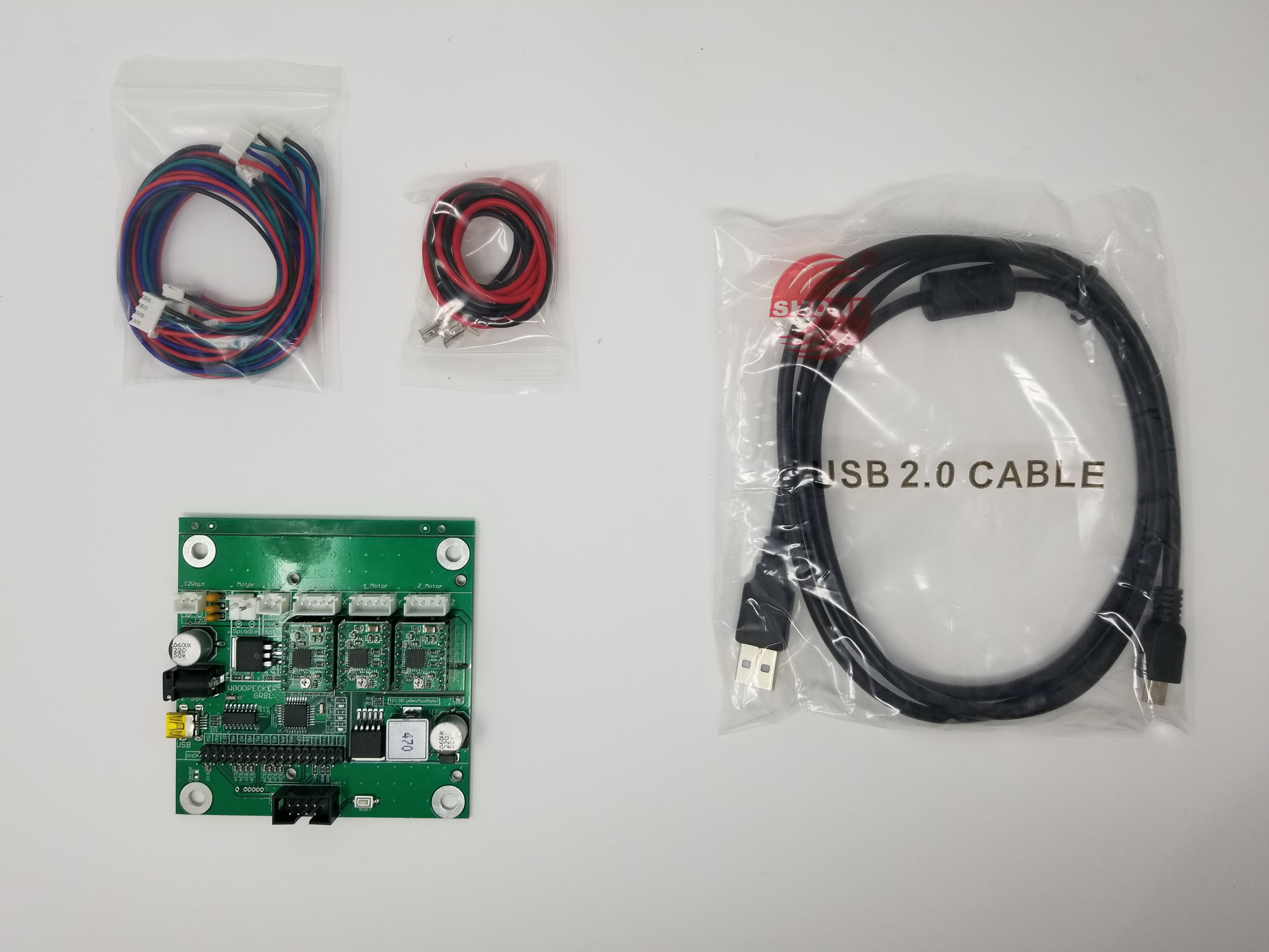
Electronics
There isn’t really much in terms of electronics, all we have to do is connect few wires – the CNC is using a Woodpecker board, and all the cables have headers for an easy connection. No soldering needed. Also the lengths of the cables were sufficient, allowing for some cable management to make it look cleaner.
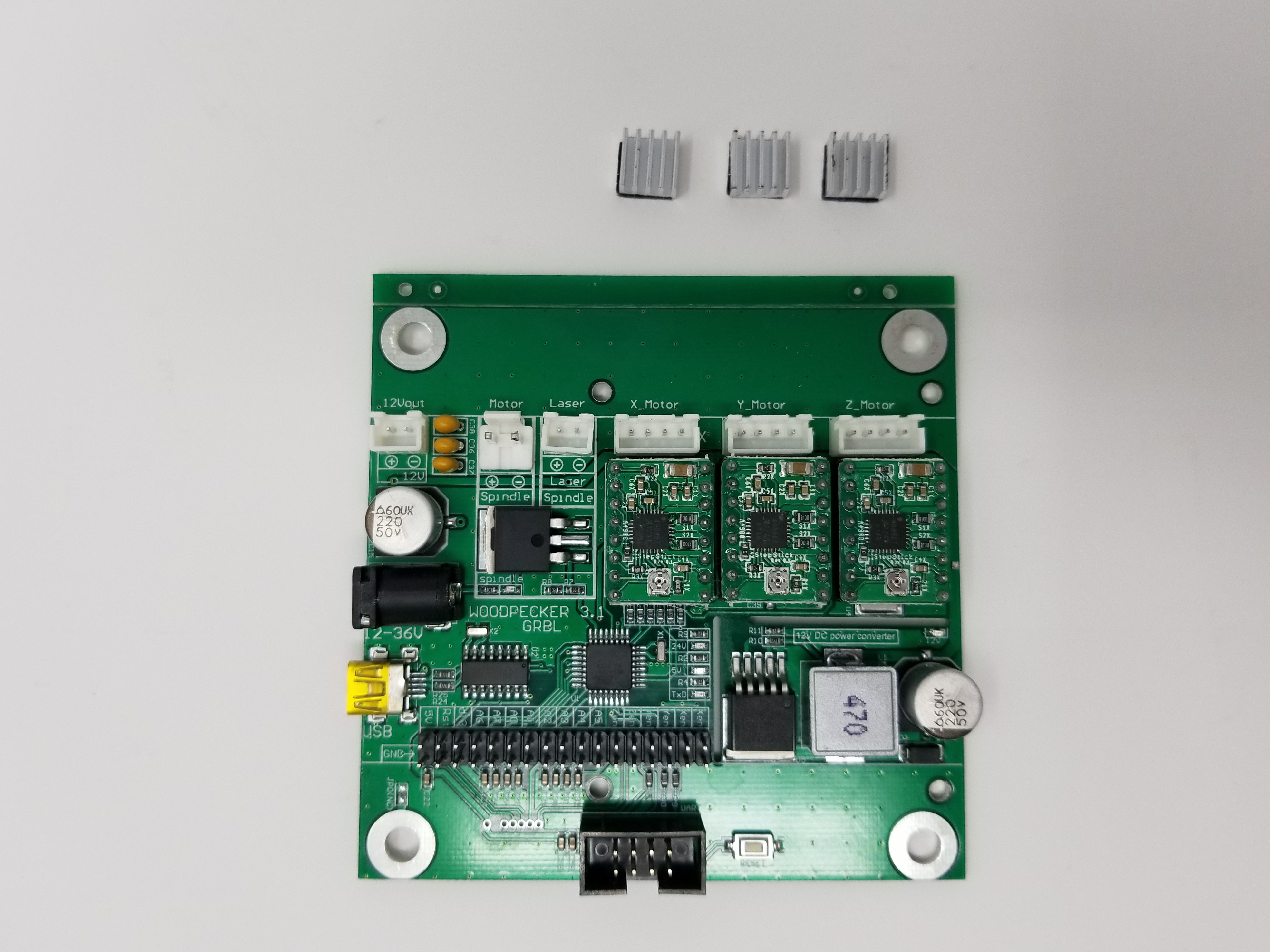
Don’t forget to put the heat sinks on the stepper motor controllers:
The board is then screwed behind the X axis motor, thanks to screw holes with a convenient spacing equal to pitch between 2 extrusions. It felt a bit “bare” to me, so I 3D printed an enclosure (see the this article for more information).
Tip: The spindle should be spinning clock-wise when you’re looking at it from the front (meaning, looking at the shaft, not at the power connectors). If it’s spinning in the opposite way the first time you power it up, simply switch the positive and negative wires at the spindle.
Now, this is where the main part of assembly ends.
However, since there are no limit switches, the machine felt very limited to me – we wouldn’t be able to make use of automatic homing and would need to be extra careful when nearing limits of each axis… This introduces additional effort and risk, and since it can be remedied cheaply and easily, I decided to add them before I start using the machine. Now, if you decide to add limit switches, you need to enable them in grbl, and set the appropriate flags to specify which direction will be used for homing cycle for X, Y and Z. Please refer to the article dedicated to such improvements: Part 3 – Updates and improvements
Testing and first engraving
OK, enough talking, see videos below for the end result 🙂
Homing (with limit switches):
Homing (with limit switches) – close-up view:
First engraving:
If you can’t tell what’s hiding under the shavings – it’s an outline of Macaw’s head 🙂
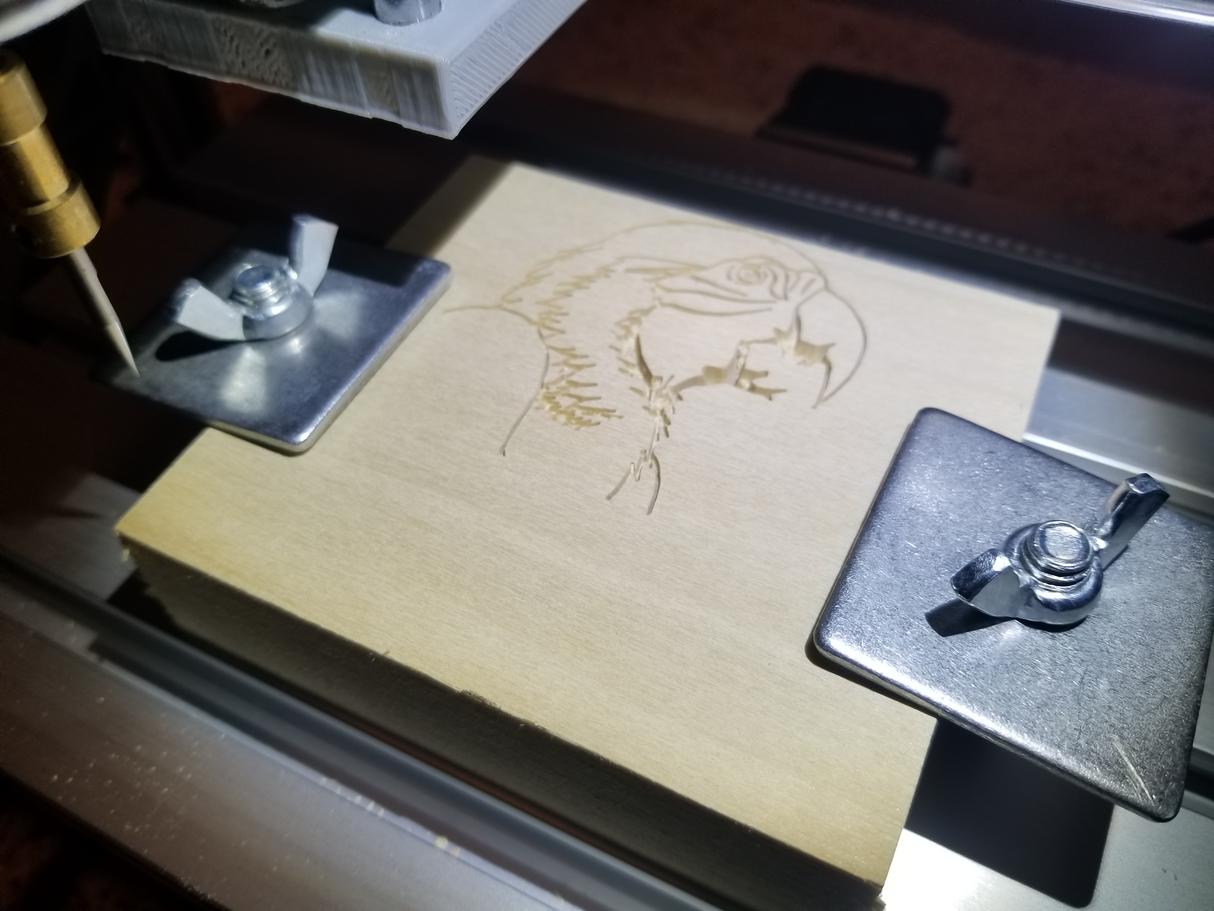

This job ran for just over 5 minutes.
Troubleshooting issues
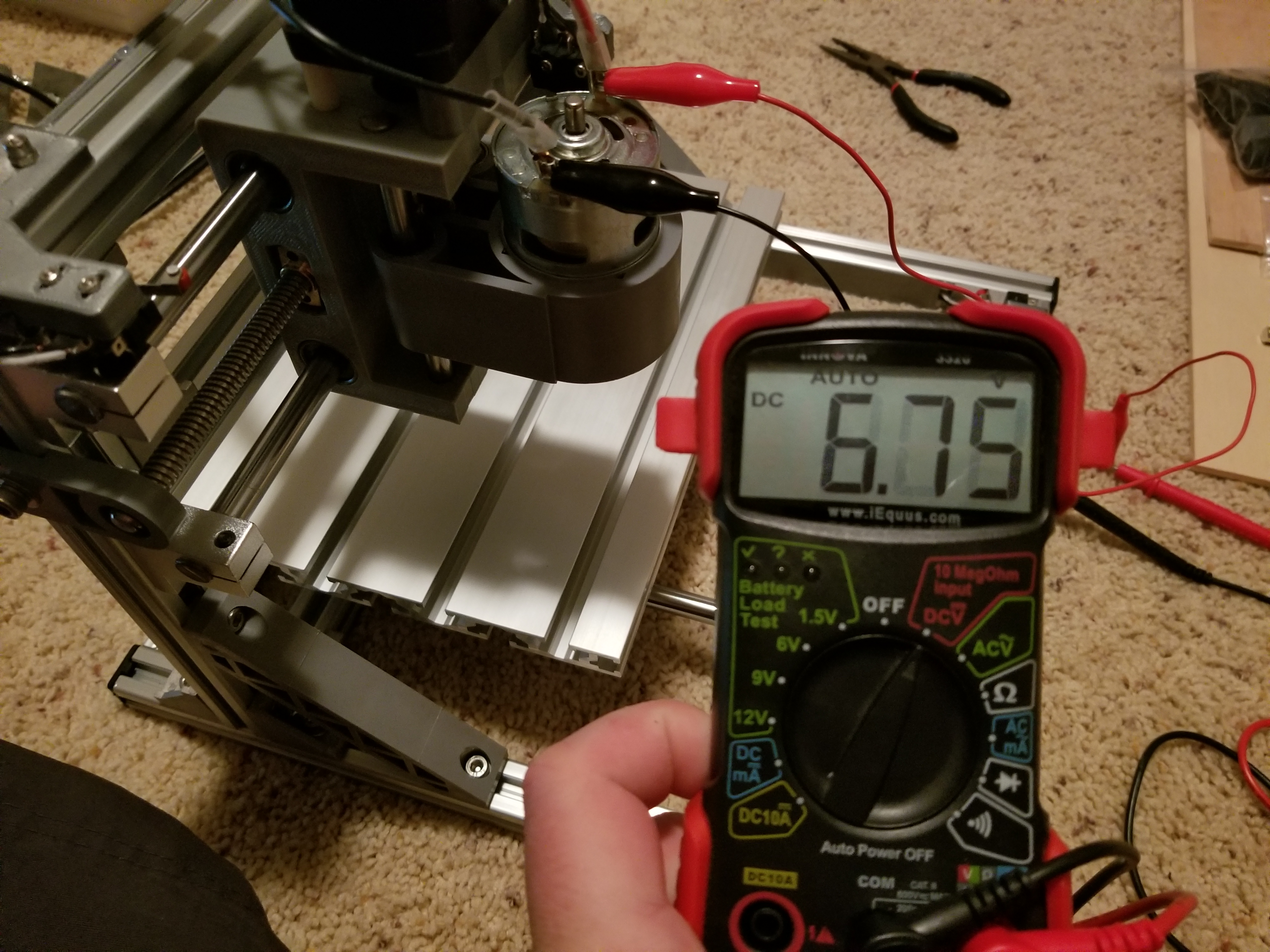
I encountered a weird problem when trying to start a job – the machine would attempt begin the cycle (by starting the stepper motors and spindle) but it wasn’t really behaving as expected. The power consumption is greater when motor/spindle starts, than under continuous operation, and this sudden surge was proving to much for my power supply. The spindle wasn’t able to start, and instead was starting to spin and stopping right at the surge when voltage was dropping:
The expected voltage at the spindle is 24V, I was getting significantly less than that, not enough to keep it running:
Potential workaround, which I was able to use with success while waiting for new power supply, was to start spindle manually through grblControl software, and then starting the job with spindle already running.
So how does the machine perform?


Leave a Reply